This is a quick set of notes/instructions explaining, for complete Houdini/ZBrush newbies (that would be me), how to move a model from ZBrush to Houdini, and to ensure that textures and normals make it along the way. This will include the creation of a
very simple shader network that will take the normal and texture map files created by ZBrush and use them in Houdini. Houdini will be used to create the UV coords, and export this as an .obj file. Prior to this evening, I wasn't sure how hard this was going to be, and I stunned at how easy it is (or perhaps I'm finally starting to grasp how the various parts of all of this are supposed to work).
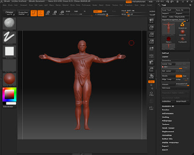
Create the model in ZBrush. If you're using ZSphere's make sure to subdivide up a number of levels *first*, then resume modeling.
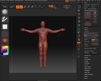
After subdivision
The reason is so that you have at least one level of subdivision, and to "tighten" up the initial sub division level 1 geometry. Without this, things may appear a little weird when you export the model to Houdini (or Maya, Modo, et al). I'll use the "Super Average Man" model supplied with ZBrush 3.1 for this. Don't forget to make the tool into a PolyMesh3D. Do your ZBrush editing/sculpting as you normally would.
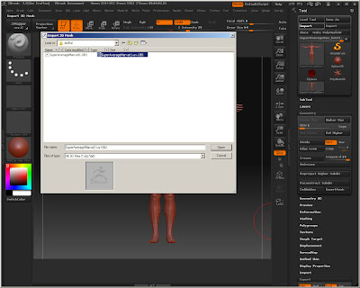
Bring the subdivision levels back down to level 1, and export the model as an OBJ file. The default export settings seem to be OK for this.
Exporting
Bring the model into Houdini. A simple way is to create a Geometry node in your scene, drop down a File SOP, and import the new .obj file you just created.
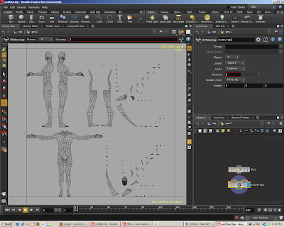
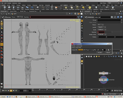
At this point we have the base model in Houdini. We need to create UV coords that we can then make use of in ZBrush for the Normal and Texture maps. One simple way to create some UV coords is to add a UV Unwrap SOP to your file node.
Switch to UV view and you can see what's happened. Houdini has unwrapped your geometry, to that point, inside a UV square. Make sure that the uv unwrap node is toggled as the render/display node, and then export the geometry as an OBJ format. This save the geometry, which is unchanged, and add the uv coordinates that were added by the UV unwrap SOP.
Exporting with UVs
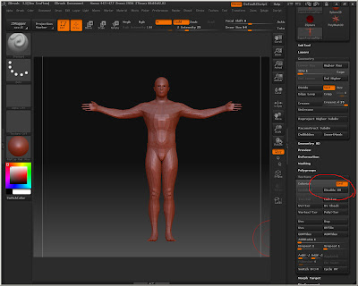
In ZBrush import the newly saved obj file, making sure that you're at sub division level 1.
Note that in the Tool palette's Texture options, the EnableUV button is disabled - meaning that it picked up the UV map in the new obj file.
At this point we can create the Normal map. Open up the ZMapper plugin. Make sure that the Object Space.nmap option is selected.
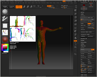
Click the Normal/Cavity Map tab, (bottom far left tab in the UI), and with the default options, click the Create NormalMap button on the far right. This will take a few seconds as the normals are calculated. Once it's finished you can exit the ZMapper. Now we have a Normal map that's selected into the Texture area of our tool. Select the map, and export it as a tif file.
Let's verify that the normals are OK by creating a shader network and a shader to use. Create a SHOP Network in your geometry container.
Enter the SHOP Network node, and add a "VOP VEX Displacement SHOP" node.
This will use the normal map data to displace the geometry. Make the node a Material by selecting the node, and hitting "Shift" + "C" keys - this will wrap your displacement node into a Material node and attach it to a sub-output node.
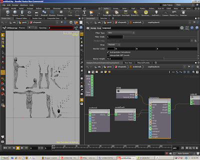
Enter the displacement node, and enter the following network:
All that's happening is the creation of a UV parameter - a special parameter that is a vecgtor type, and has it's node name and Parameter Name set to "uv" - case matters, "UV", Uv", or "uV" won't work - it's got to be "uv". This will store the current UV coordinate from the geometry network as it's being evaluated for rendering. Make sure that it's set to invisble, as we do not want to promote this in our Material parent node.
This is pushed into a UV transform node. We need to flip the data to properly handle the data output by ZBrush. There is an option in ZMapper to do this as well, but it's worth noting what cna be done in Houdini without altering the ZBrush data.
The transform output is converted from a vector to a float, and then sent to a Bump Map node. This creates the displacement, with the u and v coords send to the "s" and "t" inputs of the Bump Map node. Create another parameter for specifying the Normal Map file name by middle-clicking on the "tmap" input of the Bump Map node.
Finally connect the "dispN" output of the Bump Map to the "N" input of the final output node ("output1").
Jump up one level to the Material node, right click, and select the "Promote Material Parameters".
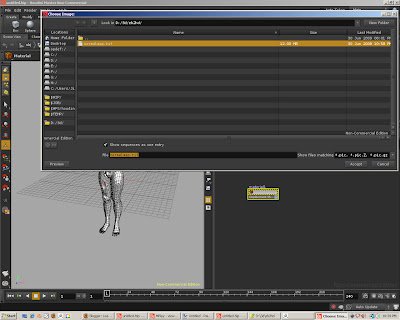
This should make the texture map parameter visible here. Enter the tif normal map file you created earlier from ZBrush.
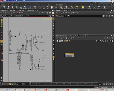
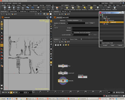
Back in the Geometry container network, add a Material node to your geometry, and select the material you just made in your SHOP network.
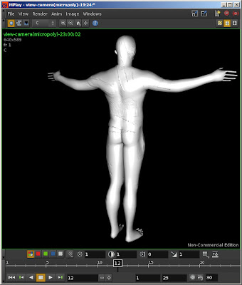
At this point you should be able to render with Mantra and see the effects of the normal map, despite the low res geometry.
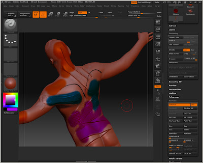
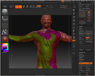
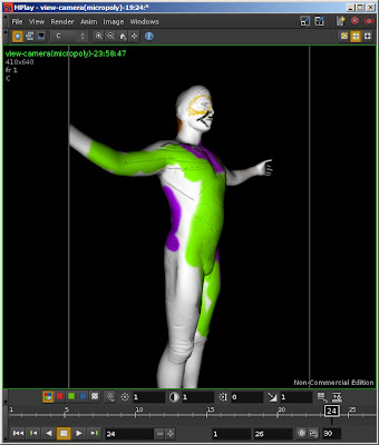
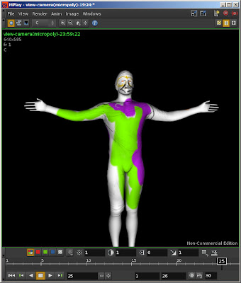
At this point I'll go back to ZBrush and poly-paint the model.
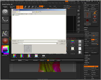
When that's done, go to the Tools > Texture sub-palette and click Col>Txr. This will create a texture map, based on the UV coords we had earlier, and colorize it according to what you've painted on the model/tool. Export this texture out as a tif for use in Houdini.
Export
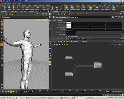
To use this in Houdini we need to modify our SHOP material. Go back to the material node and edit it. Add a new "VOP VEX Surface Shop" node and attach it to the suboutput1's "next" input.
Enter the surface node and create the following network.
We'll start with a similar setup to the previous normal displacement network. Add a uv parameter, flip it's V vector component, and separate out the individual U and V components. These go into a texture node, into the "s" and "t" inputs. The output of the texture, the color, is sent into the "diff", or diffuse color, input of a Lambert node (you could use something else, this is just a simple example). The "clr" output is then connected to the "Cf" input of the final output node. Render with Mantra, and
Voila! a textured model!
Credits:
The normal map stuff was gleaned from
this post at odforce for starters. I found a tutorial on ZMapper elsewhere. The bits about initial subdivision in ZB I picked up from the 3D Buzz ADP tutorials.


